PwrPk Main Menu and Toolbar
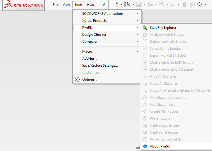
The Main menu can be found in the Tools tab across the top of the application. Simply click on Tools -> PwrPk and the following menu will appear.
The PwrPk toolbar can be found by Right Clicking in the SOLIDWORKS® menu area to bring up the customize menu. Locate PwrPk in the list and turn on the toolbar. The toolbar can be customized the same as any toolbar.
A simple yet quick command to open Microsoft File Explorer in a new window based on the file location of the active document. The directory of the active document will be used as the starting directory when explorer is opened. If the active document has not been saved then this command will default to the system 'My Documents' directory. This command is used to gain quick access to exported files or screen captures of the active document without having to navigate to get to them.
By selecting one or more sketches a dialog chart will report entity counts, and spline counts of the selected sketches.

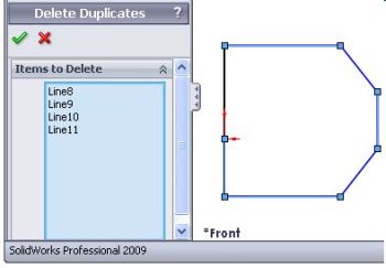
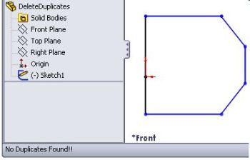
First select the sketch from the feature tree at anytime even while editing the sketch. Click the delete duplicates icon and the command will compare each line and arc in the sketch for duplicates and if found will list the duplicate entities in the property manger page as items to delete. The command rounds off the at 1/1000 mm so most imported data containing duplicates with small rounding errors will be selected for deletion. If no duplicates are found the lower left frame of SOLIDWORKS® will indicate no duplicates found and the property manager page will not be displayed. Simply press the ok check mark to delete all the entities in the duplicates list or click the cancel x to exit without deleting. You can undo the delete after the command is finished if required.
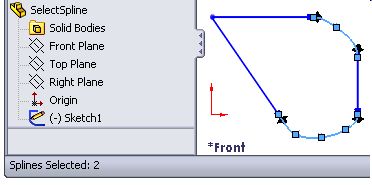
First select the sketch from the feature tree at anytime even while editing the sketch. Click the select splines icon and the command will find and select all splines in the selected sketch. When this command completes the lower left frame of SOLIDWORKS® will indicate the number of splines found. The command will work if the sketch is simply selected from the feature tree and will end in edit sketch mode for the selected sketch. This allows you to simply press the delete key to delete all the splines found in the selected sketch. This command if very useful for imported data containing a mix of splines with lines and arcs to find and highlight all the splines for deletion.
![]() Export Marked Sketches (IGES
Or DXF)
Export Marked Sketches (IGES
Or DXF)
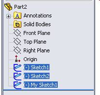
Exports all sketches containing "-EDM" or "-CAM" in their name. This command only exports lines and arc in IGES or DXF format. The exported sketches are placed on named levels. Not all CAD/CAM packages support level name for IGES imports so the level names may not show. The names are related to the feature and sketch name from SOLIDWORKS®. Each pair of sketches from a feature are exported using different colors. For example a loft feature containing 2 sketches would have one sketch red and the other sketch blue in the exported file. Sketeches marked "-EDM" ignore construction geometry and sketches marked "-CAM" will export construction geometry as centerlines. These exported files are generally used for ease in programming CAM software such as Mastercam® or for importing geometry into FEA Simulation packages.
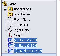
Select single or multiple sketches from the feature tree and select this command. Each sketch will be renamed by adding EDM to the existing name. This name is used by the Export Sketch command to select the sketches you wish to export.
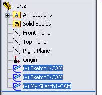
Select single or multiple sketches from the feature tree and select this command. Each sketch will be renamed by adding CAM to the existing name. This name is used by the Export Sketch command to select the sketches you wish to export.

In a part, selecting hide all sketches cycles through the
feature tree hiding all sketches including sketches absorbed by
features
In an assembly, selecting hide all sketches cycles through each
open component in the assembly to hide all sketches found in
each part.
In a part, selecting show all sketches cycles through the feature tree
showing all sketches including sketches absorbed by features.
In an assembly, selecting show all sketches cycles through each open
component in the assembly to hide all sketches found in each part.
Sketches containing "-EDM" or "-CAM" in their name will be exported using the command Export
Marked Sketches.
![]() Show All Marked Sketches (CAM/EDM)
Show All Marked Sketches (CAM/EDM)
In a part, selecting show all sketches cycles through the feature tree
showing all sketches that contain "-EDM" or "-CAM" in their name including sketches absorbed by features.
In an assembly, selecting show all sketches marked for export cycles through each open
component in the assembly to show all sketches that contain "-EDM" or
"-CAM" in their
name.
Start this command to bring up the Property Manager Page shown below.Select exactly 2 sketches to create a new 3D sketch connecting the endpoints. Both sketches must contain the same number of endpoints. The endpoints are synchronized based on a best fit. The below picture shows the 2 sketches to use for the loft.
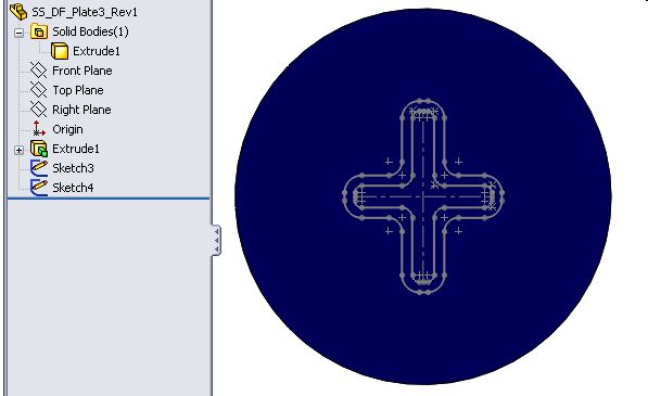
Select Sketch 3 and Sketch 4. As you select the sketch the entity counts will be updated and a check for loft section is preformed.
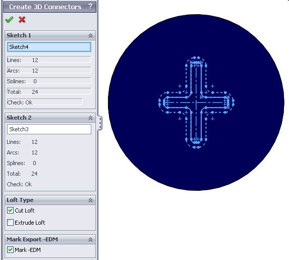
After all selections have been made, select the OK check mark to complete the command:
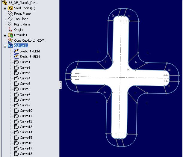
- A 3D sketch is created syncronizing with lines the 2 sketches. The sketch will be named Con: Loft Feature Name plus -EDM if Mark is selected.
- Curves will be created for each line in the 3D Sketch. These will be used as guide curves in the loft.
- If selected, the cut or extrude loft will be created using the 2 selected sketches. The curves will be added as guide curves to the loft feature.
- The sketches will be marked with "-EDM" if selected in the property manager
For each component in an assembly, sketch text is added to the derived sketch. There are many options including cutting a pocket for the text, and cutting the text into the solid.
Create a Solid form to remove from the main body. Select the face that will be removed to create the pocket. This command will create a copy of the form solid, remove the face to create a surface body of the pocket, then remove the form from the main body. The main body is determined by the largest volume. The surface body color will be cycled randomly through 16 colors.
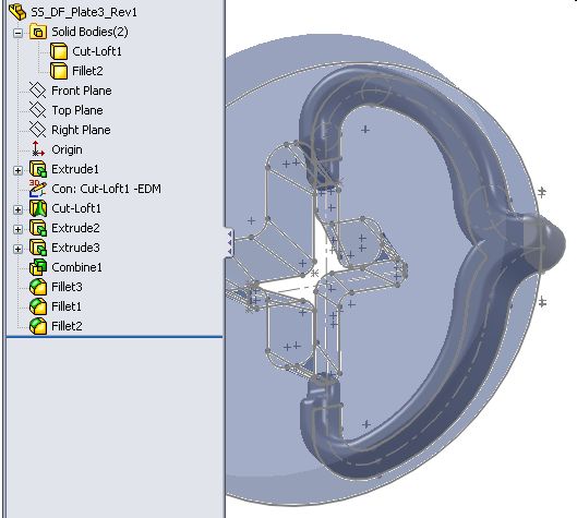
Select the face of the Solid Body that creates the pocket and then select the mill pocket icon.
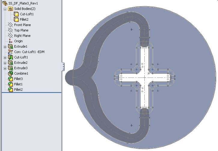
The command will perform the following:
- Make a copy of the form body to use to create the surface
- Delete the face of the copied body thus creating the Surface body. The surface body will be used by the CNC programmer to cut the pockets. The pockets can intersect through holes in the model but the surface body will not reflect these holes making it easy to CNC program the pocket.
- Change the color of the surface body.
- Combine subtract the original form body with the main body as determined by the largest volume.
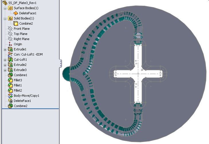
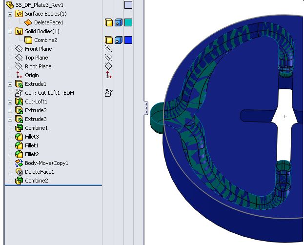
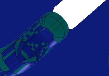
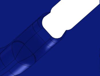
Notice the pocket will intersect the through hole. The Surface body does
not reflect the intersection making it easy to CNC program the pocket.
Used to export multiple components in multiple formats from a single command. From Assembly or from an individual part, a property Manager Page is displayed listing each component of the assembly or the single part to select which components will be exported. The checkboxes allow multiple selections of the export file types. The auto checkboxes indicates how the export files will be named. If auto is not selected each export file will display the save window to name the file. If the use sub-directory checkbox is checked directories will be created automatically based on the component file name. All selected files types will be saved in the newly created directory.

Similar to the SOLIDWORKS® command for screen captures but this command captures the current screen and saves it to a Jpeg file. The filename will be generated automatically based on existing files in the directory. It will be named according to the active document name plus -pwrpk-xxx.jpg.

Similar to the SOLIDWORKS® command for screen captures but this command captures the current screen and saves it to a Tiff file. The filename will be generated automatically based on existing files in the directory. It will be named according to the active document name plus -pwrpk-xxx.tif

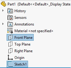
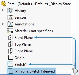
Similar to the SOLIDWORKS® command Derived Skecth except the sketch name will be renamed to include the original sketch name. First, select a plane and sketch then select this command. A Derived sketch will be created and renamed. The derived sketch from Sketch1 will be named From: Sketch1 derived. This helps to identify the source sketch.
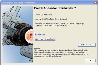
This command will show the current version of PwrPk installed. It contains links to the PwrPk website. If PwrPk is being run using an evaluation license it will display the purchase website link and a button to input a purchased license key.
